GPIO and pin muxing
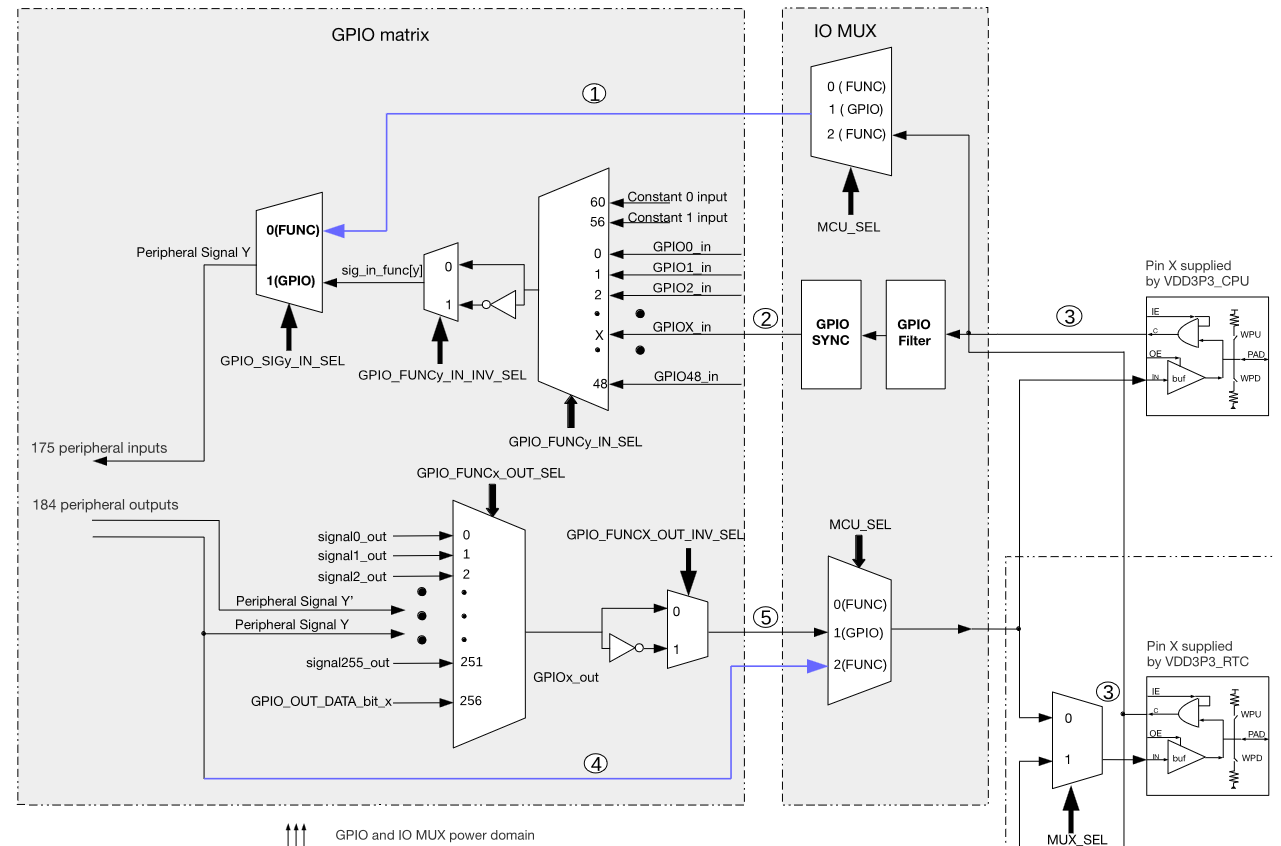
Take a look at the esp32s3 TRM chapter 6.3, table 6.2 and table 6.3 to understand relation between the peripheral signals, IO MUX and the GPIO matrix. Teaser picture:
IO MUX pin settings (selected function, drive strength, pull-up, pull-down, input enable) are controlled by the children of the iomux: pinctrl@60009000 node, like this:
&iomux {
	spi2_pins: spi2_pins {
		pinctrl-single,pins = <
			PIN(9)  (FUN0_20MA)			/* CS1 */
			PIN(10) (FUN_SEL(4) | FUN_DRV_20MA)	/* CS0 */
			PIN(11) (FUN_SEL(4) | FUN_DRV_40MA)	/* MOSI */
			PIN(12) (FUN_SEL(4) | FUN_DRV_40MA)	/* SCK */
			PIN(13) (FUN_SEL(4) | FUN0_20MA_IE_WPU)>;/* MISO */
	};
};
These properties cannot be changed at runtime (short of writing directly to IO_MUX_n_REG registers).
When there's no direct connection for the function in the IO MUX (e.g. UART2 signals are not there) or the pin with direct connection cannot be used, a function may be routed through the GPIO matrix to a different GPIO and connected to a different pin. These settings are controlled by the children of the nodes gpio_out_mux: gpio_out_mux@60004554 and gpio_in_mux: gpio_in_mux@60004154. Numbering schemes are different for output and input muxes. E.g. for the ouput mux a GPIO index is mapped to a peripheral signal (table 6.2):
&gpio_out_mux {
	spi2_gpio_out: spi2_gpio_out {
		pinctrl-single,pins = <
			GPIO_FUNC_OUT_SEL(9) 111>;		/* SPI2 CS1: GPIO9, signal 111 */
	};
};
For the input mux a peripheral signal is mapped to a GPIO index:
&gpio_in_mux {

	uart2_gpio_in: uart2_gpio_in {
		pinctrl-single,pins = <
			GPIO_FUNC_IN_SEL(18) 5>;		/* U2RXD: signal 18, GPIO5 */
	};
};
All used pinctrl phandles are then mentioned in the device's pinctrl property:
&spi2 {
	pinctrl-0 = <&spi2_pins &spi2_gpio_out>;
	pinctrl-names = "default";
};
Other properties of a GPIO pin (input/output, normal/open drain, interrupt type) can be controlled through the GPIO API or through the device tree connection for the pin, like the pins 6, 7 and 8 have here:
i2c0 {
	#address-cells = <1>;
	#size-cells = <0>;
	compatible = "i2c-gpio";

	sda-gpios = <&gpio0 6 (GPIO_ACTIVE_HIGH | GPIO_OPEN_DRAIN)>;
	scl-gpios = <&gpio0 7 (GPIO_ACTIVE_HIGH | GPIO_OPEN_DRAIN)>;

	pinctrl-0 = <&i2c0_pins>;
	pinctrl-names = "default";

	mpu6050@68 {
		compatible = "invensense,mpu6050";
		reg = <0x68>;
		interrupt-parent = <&gpio0>;
		interrupts = <8 IRQ_TYPE_EDGE_RISING>;

		pinctrl-0 = <&accelerometer0_pins>;
		pinctrl-names = "default";
	};
};
GPIO pins may need to be in a specific state after boot, but there may be no device that would drive them. In that case they can be brought to that state by the gpio-hog nodes added under the gpio controller node, see Documentation/devicetree/bindings/gpio/gpio.txt for the details.